Hengshui Aiye Machinery Equipment Co., Ltd.
 Business License
Main Products: rubber dam, Inflatable rubber dams, Hydraulic elevator dam, Cast iron gates

The Working Principle of Air-supported Dams
Mrs. Wendy
June 25, 2025
1. Structural Components
1.1 The Airbag
The airbag is a crucial component of the air - supported dam, typically constructed from multiple layers of high - strength materials. For instance, it often consists of layers of NN66 or aramid fiber as the skeleton, which are combined with special rubber compounds. These materials endow the airbag with high strength and durability.
The airbag's performance is remarkable. Its working pressure generally ranges from 0.7 - 0.8MPa, and it is designed with a safety inflation pressure of up to 8 kilograms. This gives it a safety factor 15 times that of traditional rubber dams. The outer layer of the airbag is made of EPDM polymer, which has excellent weather - resistance and ozone - aging resistance, ensuring a service life of more than 50 years.
1.2 The Water - retaining Shield Plate
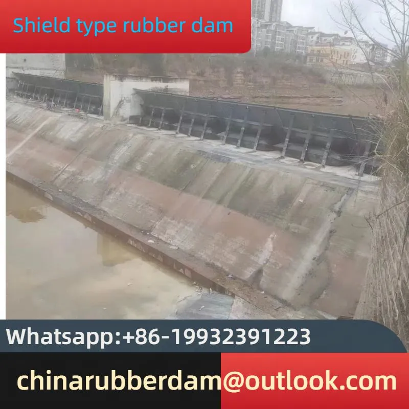
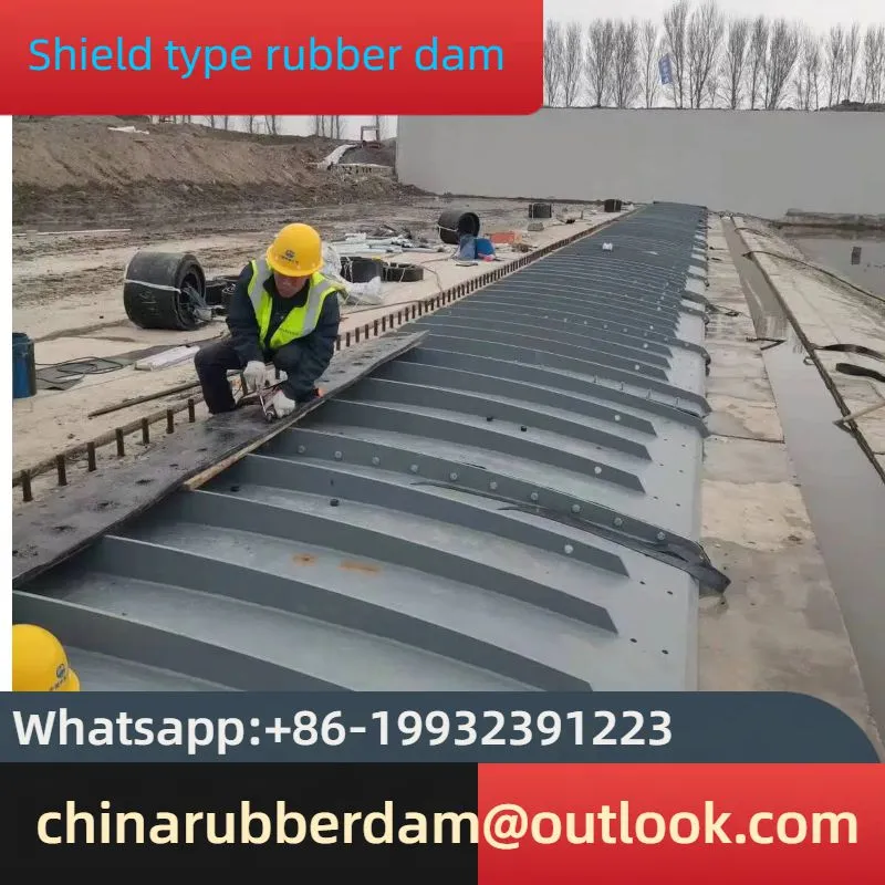
The water - retaining shield plates are usually made of stainless steel or carbon steel (with surface treatments such as polyurea coating or hot - dip galvanizing to enhance corrosion resistance). Each shield plate unit is typically about 5m in length, and the units are connected by high - strength rubber composite strips in a flexible manner. Structurally, they are fabricated from thick steel plates (usually 16mm or more) and have an arc - shaped design. On the water - facing side, reinforcement ribs are welded to enhance the plate's strength and stability.
2. Operating Mechanism
2.1 Dam - raising Process
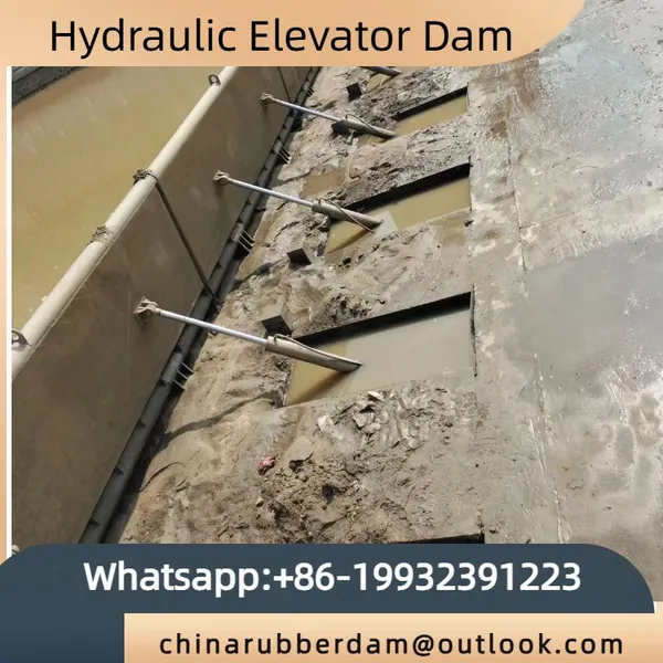
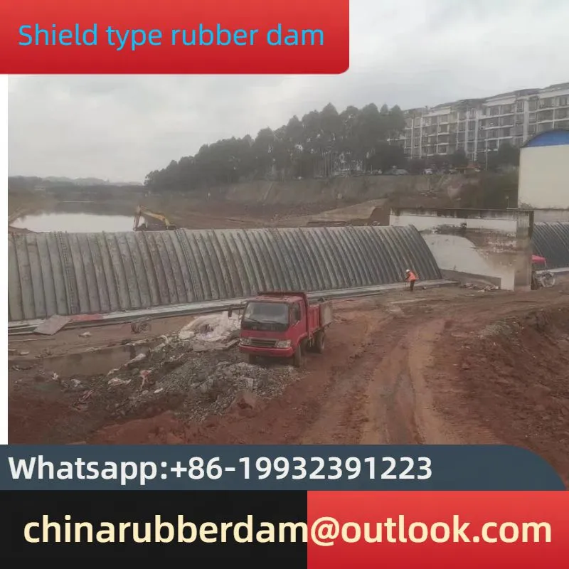
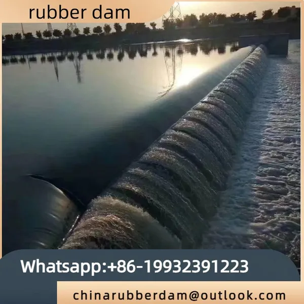
When it is necessary to raise the dam to store water or adjust the water level, the air - supply system, which is part of the control system, starts to work. Compressed air is pumped into the airbags located beneath the shield plates. As the air fills the airbags, they gradually expand. The expansion of the airbags exerts an upward force on the shield plates. Since the shield plates are connected to the dam foundation through specific hinge - like structures (such as bolts with washers and hinges, as described in some practical cases), the upward force from the airbags causes the shield plates to rotate around the connection points at the bottom. As more air is pumped in, the shield plates are gradually lifted to the desired height, forming a barrier to retain water. The height to which the shield plates are raised can be precisely controlled by regulating the amount of air pumped into the airbags. This allows for accurate control of the upstream water level, which is crucial for various applications such as power generation, irrigation, and water storage for urban use.
2.2 Dam - lowering Process
In situations where it is necessary to lower the dam, such as during flood discharge or when the water level needs to be adjusted downward, the control system initiates the deflation process. The air in the airbags is released through the exhaust valves. As the air pressure inside the airbags decreases, the upward force they exert on the shield plates also reduces. Under the influence of gravity and the water pressure from the upstream side (if there is still water retained), the shield plates gradually tilt and fall back to their original positions, lying flat on the riverbed or dam foundation. This process enables the smooth passage of water downstream, ensuring flood control safety and maintaining the natural flow of the river. When the shield plates are in the lowered position, the airbags are protected beneath them, reducing the risk of damage from floating debris, ice floes, or the impact of high - velocity water flow.
2.3 Control System
The control system of the air - supported dam plays a vital role in its operation. It can be equipped with various sensors, such as pressure sensors to monitor the air pressure inside the airbags and level sensors to detect the upstream and downstream water levels. These sensors continuously send real - time data to a central control unit, which is often a Programmable Logic Controller (PLC). Based on pre - set parameters and the received sensor data, the PLC can automatically control the operation of the air - supply and exhaust systems. For example, if the upstream water level exceeds a certain threshold during a flood, the PLC will quickly trigger the exhaust valves to release air from the airbags, causing the dam to lower and allow for flood discharge. In addition, the control system can also be remotely operated, allowing operators to control the dam's operation from a control room located at a distance. This is especially convenient for dams located in remote areas or in situations where on - site operation may be difficult or dangerous.
Share
Recently Posted
-
Water Stop Steel Plate: Material and Applications
June 26, 2025IntroductionWater stop steel plate, also known as steel water stop, steel water bar, or anti - seepage steel strip, is a crucial s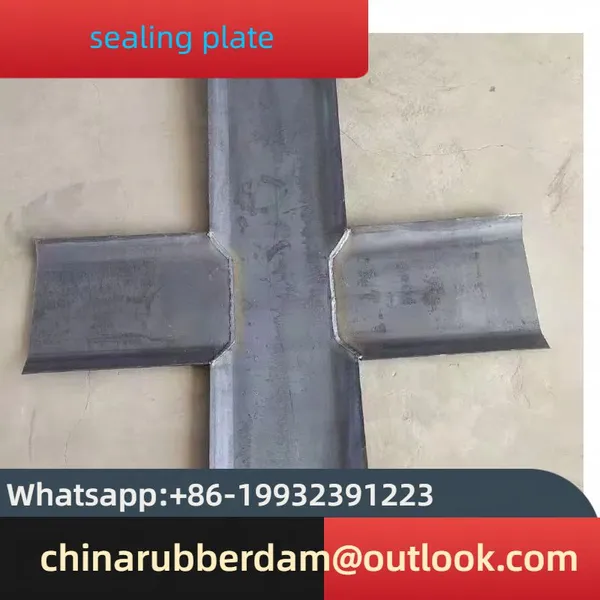 Read More
 -
Steel and Copper Plates Play Key Roles in Architectural Waterproofing
June 26, 2025In the realm of construction, ensuring effective waterproofing is of utmost importance. Steel and copper plates have emerged as cr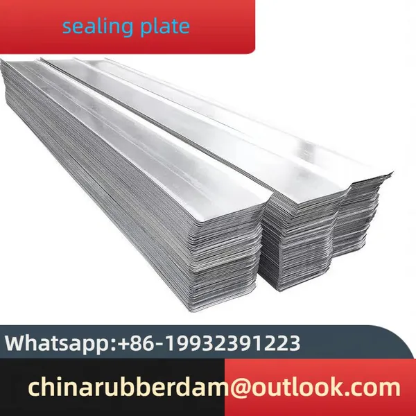 Read More
 -
Installation Steps and Precautions of Gabion Nets
June 26, 2025In recent infrastructure and environmental protection projects, gabion nets have emerged as a popular choice due to their durabili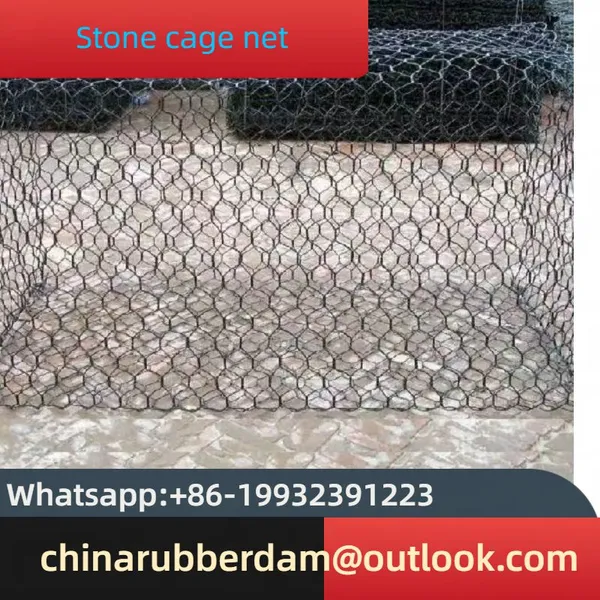 Read More
 -
Applications of Gabion Mesh: Protecting and Enhancing the Environment
June 26, 2025In recent years, gabion mesh has emerged as a versatile and effective solution for a wide range of applications, particularly in t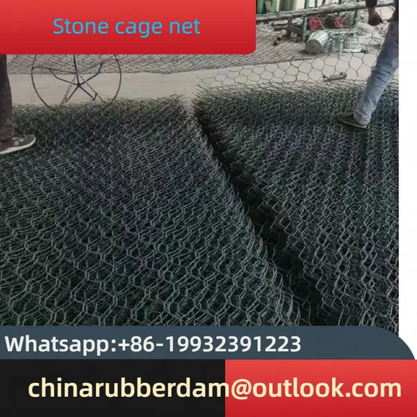 Read More

Contact Us
Recommended Products
-
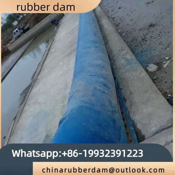
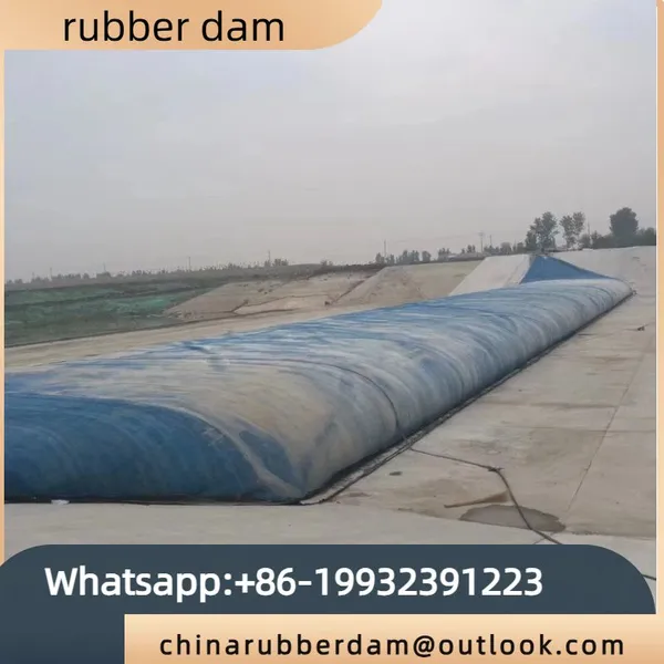
 River Water Storage Landscape Rubber Sluice Bag Rubber Dam Water Filling River Blocking Dam Embankment Inflatable DamUS$ 5200 - 6500MOQ: 1 Bag
 -
Small Rubber Dam Slope Inflatable Landscape Dam Can be CustomizedUS$ 5200 - 6500MOQ: 1 Bag
-
Whole Slope Landscape Ecological Rubber Dam Spot Circular Rubber DamUS$ 5200 - 6500MOQ: 1 Bag
-
Customized Production of Book Style Inflatable Flood Control Dam, Retaining Dam, Steel Wire Boneless Rubber DamUS$ 5201 - 6500MOQ: 1 Bag
-
Small Inflatable Rubber Dam Water Injection Rubber Dam Bag Dam Source ManufacturerUS$ 5201 - 6500MOQ: 1 Bag

-
Supply Rubber Dam With Dam, Inflatable Dam for Sale in StockUS$ 5200 - 6500MOQ: 1 Bag
-
Large Scale Hydraulic Engineering Hydraulic Steel Dam Landscape Hydraulic Dam in Hebei, China, Replica Steel Gate Rubber Dam for Retaining DamUS$ 5200 - 6500MOQ: 1 Bag
-
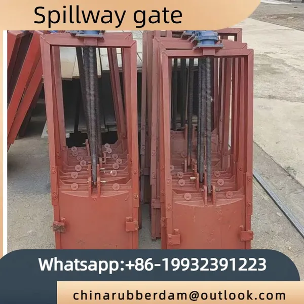
Cast Iron Square Gate/Source Manufacturer Cast Iron Gate SFZ-2000x2000 Matched With Electric Hoist Screw RodUS$ 999 - 1200MOQ: 10 Pairs
-
Steel Gate Source Manufacturer Supplies Stainless Steel Gate ZSZ-2400x2400 Water Stop GateUS$ 999 - 1200MOQ: 10 Pairs
-
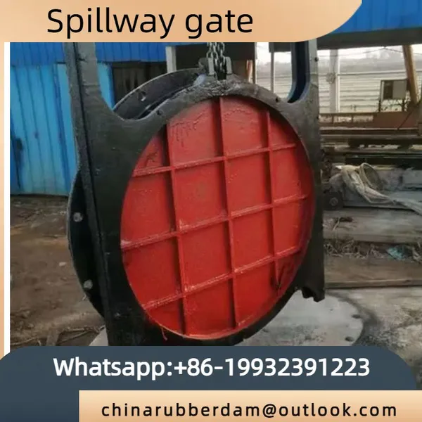
Round Copper Inlaid Cast Iron Gate/Manufacturer Produces Concealed Cast Iron Gate AYZ500 Hoist Cast Iron GateUS$ 999 - 1200MOQ: 10 Pairs
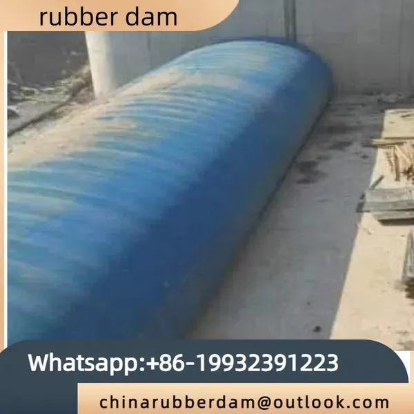
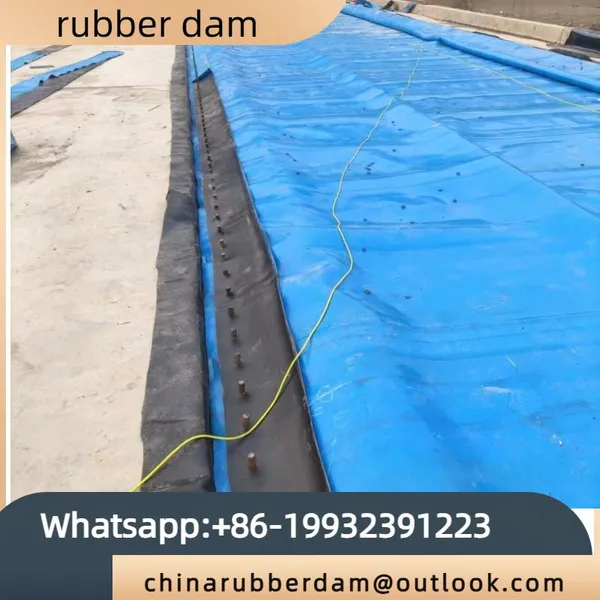
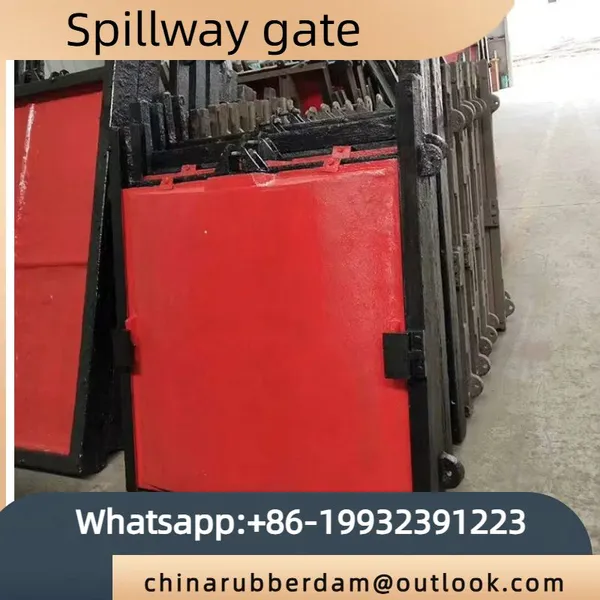
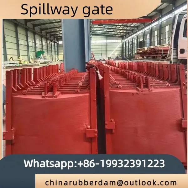
-
Stainless Steel Gate Manufacturer Produces ZSZ Type Water Stop Gate, Two-way Water Control Gate, Customized in Hebei, ChinaUS$ 999 - 1200MOQ: 10 Pairs
-
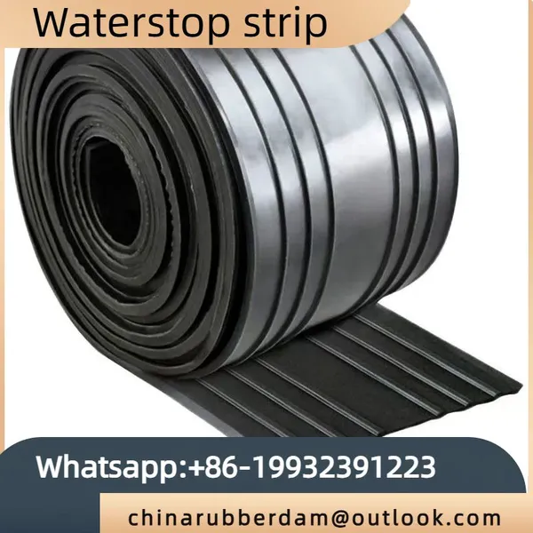
Steel Edge Rubber Waterstop Manufacturer in Stock, Wholesale in Large Quantities, With Good Sealing and Detachable Rubber WaterstopUS$ 50 - 79MOQ: 100 Meters
-
Construction of Water Injection Rubber Dam Factory, River Interception Dam, Gas Shield Dam Interception Dam ProjectUS$ 5200 - 6500MOQ: 1 Bag
-
Slope Pillow Type Water Filled Rubber Dam Construction Rubber Dam Solid FactoryUS$ 5199 - 6500MOQ: 1 Bag
-
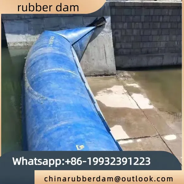
New Rubber Dam Garden Style Dam, Simple Dam, Automatic Lifting Rolling Dam, in StockUS$ 5200 - 6499MOQ: 1 Bag
-
Customized Automatic Lifting Dam for Horizontal Steel Dam Under Hydraulic Supply, River Interception, Water StorageUS$ 5200 - 6600MOQ: 1 Bag
-
Large Supply of Inflatable Rubber Dams for River and Water Interception Without Overlapping JointsUS$ 5200 - 6500MOQ: 1 Bag
-
Repair and Replace Small River Flood Prevention and Control Dams, Air Shield Dams, Seamless Overlapping Rubber DamsUS$ 5200 - 6500MOQ: 1 Bag
-
Factory Sales of Slope Type Water Filled Rubber Dam. Chinese Strong Merchants Can Customize According to Their PicturesUS$ 5200 - 6500MOQ: 1 Bag
-
The Manufacturer Supplies a Large Number of ZSZ Type Water Gates, Bi-directional Water Gates, Stainless Steel Gates, and Various Types of GatesUS$ 1000 - 1201MOQ: 10 Pairs